Lab 2 - 6502 Assembly Language
- Jan 22, 2020
- 4 min read
Updated: Feb 1, 2020
In this lab, we experiment with the Bitmap emulator to see what results we get. Here you will see the outcome of the lab as well as some notes. To test the codes you can check this Emulator ( http://6502.cdot.systems/)
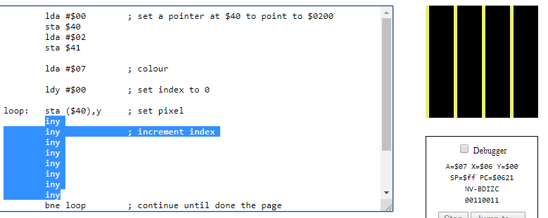
Bitmap Code used on the emulator
lda #$00	; set a pointer at $40 to point to $0200
	sta $40
	lda #$02
	sta $41

	lda #$07	; colour

	ldy #$00	; set index to 0

loop:	sta ($40),y	; set pixel

	iny		; increment index
	bne loop	; continue until done the page

	inc $41		; increment the page
	ldx $41		; get the page
	cpx #$06	; compare with 6
	bne loop	; continue until done all page
- Add 'tya' after the loop: label and before the sta($40),y instruction:
What visual effect does this cause, and how many colours are on the screen? Why?
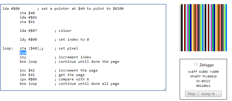
TYA means Transfer A to Y meaning that every time there's a value in Y this will increment. And with A this will define the colours that we see on screen. There are 16 colours on the screen that are represented from 0000 to 1111. Once the last number is hit, the colour sequence will repeat again.
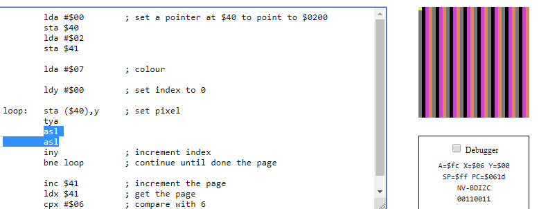
- Add 'lsr' after tya:
What visual effect does this cause, and how many colours are on the screen? Why?
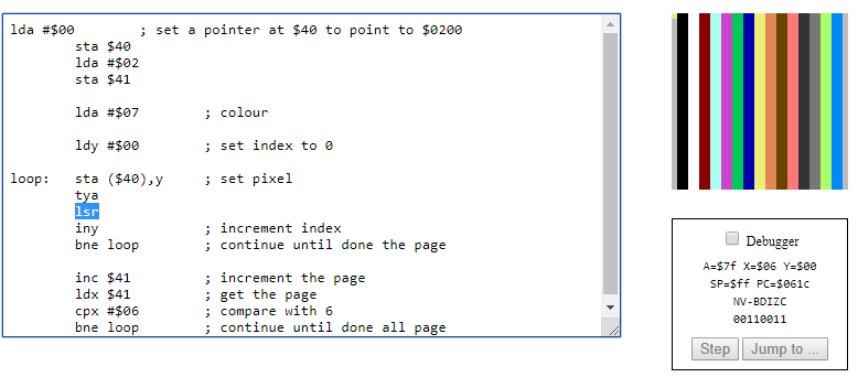
LSR means Logical Shift Right. This means that shift every colour by right bit because of this we can see on the screen that the colours take two bits of space instead of one like the example above. That's why the width of the colour becomes wider and we can see there are 16 colours.
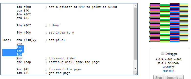
-Test with two, three, four, and five lsr instructions in a row. Describe and explain the effect in each case.
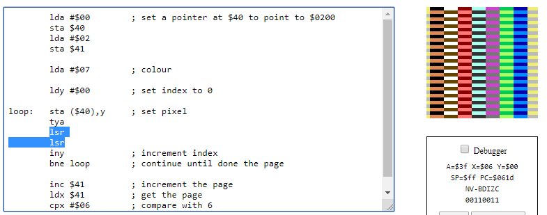
Every time we write LSR twice or three times in a row, the value will shift right twice or three times, meaning that the colours will paint 2*2 or 2*2*2 times. Therefore, for each time an LSR is repeated the width is wider 2^ the number of LSR used.
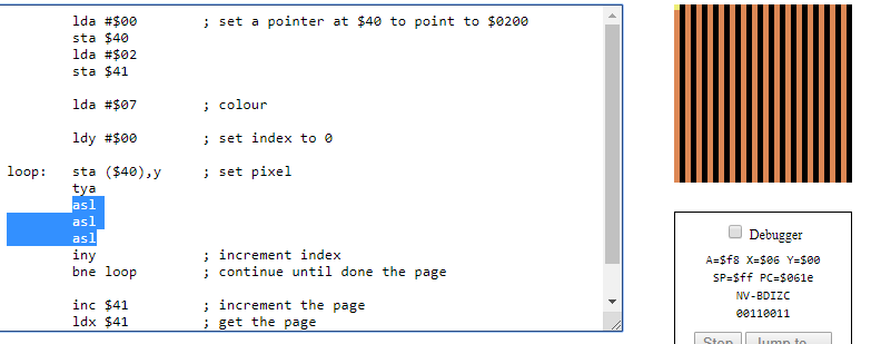
-Test with two, three, four, and five asl instructions instead of lsr instructions in a row. Describe and explain the effect in each case.

ASL means Arithmetic shift left meaning that when adding in between a TYA and STA, this will shift value in A shift left. Therefore, as seen on the screen only half of the colours are displayed for each bit.
When we add more ASL, it will shift the value depending on how many times it is repeated on the code. For example, when we add 2 ASL is repeated twice or when we add 3 ASL is repeated three times. Only a quarter of the colours will be displayed in each bit. Therefore, for each time an ASL is repeated the colour shortens 2^ the number of ASL used.
-Test with one to five consecutive iny instructions. Describe and explain the effect in each case.
INY -> Increment Y
INY with an odd number
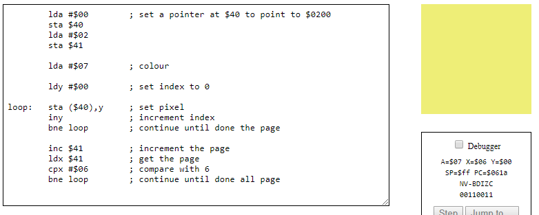
INY used with odd numbers will fill all bits with yellow but in a checkboard style. The more INY we add the slower the process is, because of that the Y index increases making it farther to reach 0 when the loops end.
INY with pair number
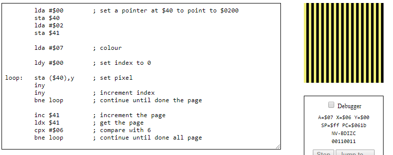
INY used with pair numbers will fill all yellow bits that are pair hence why we can see a stripe pattern on the screen. The more INY used the wider the stripes become.
Writing Code, Part 1
- Draw a green line across the top of the bitmap screen and a blue line across the bottom.
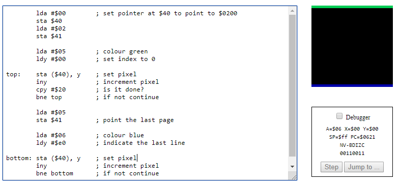
lda #$00 ; set pointer at $40 to point to $0200
sta $40
lda #$02
sta $41
lda #$05 ; colour green
ldy #$00 ; set index to 0
top: sta ($40), y ; set pixel
iny ; increment pixel
cpy #$20 ; is it done?
bne top ; if not continue
lda #$05
sta $41 ; point the last page
lda #$06 ; colour blue
ldy #$e0 ; indicate the last line
bottom: sta ($40), y ; set pixel
iny ; increment pixel
bne bottom ; if not continue
Writing Code, Part 2
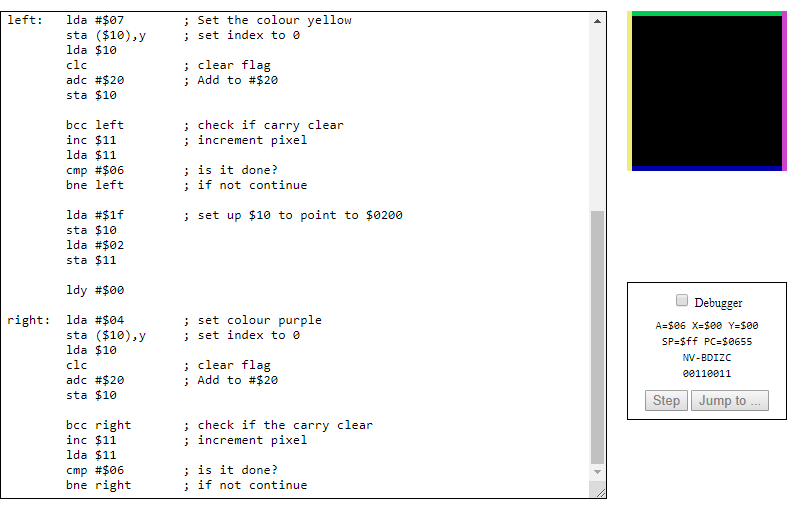
- Extend the previous code to draw a yellow line down the left side of the screen and a purple line down the right side
lda #$00 ; set pointer at $40 to point to $0200
sta $40
lda #$02
sta $41
lda #$05 ; colour green
ldy #$00 ; set index to 0
top: sta ($40), y ; set pixel
iny ; increment pixel
cpy #$20 ; is it done?
bne top ; if not continue
lda #$05
sta $41 ; point the last page
lda #$06 ; colour blue
ldy #$e0 ; indicate the last line
bottom: sta ($40), y ; set pixel
iny ; increment pixel
bne bottom ; if not continue
left: lda #$07 ; Set the colour yellow
sta ($10),y ; set index to 0
lda $10
clc ; clear flag
adc #$20 ; Add to #$20
sta $10
bcc left ; check if carry clear
inc $11 ; increment pixel
lda $11
cmp #$06 ; is it done?
bne left ; if not continue
lda #$1f ; set up $10 to point to $0200
sta $10
lda #$02
sta $11
ldy #$00
right: lda #$04 ; set colour purple
sta ($10),y ; set index to 0
lda $10
clc ; clear flag
adc #$20 ; Add to #$20
sta $10
bcc right ; check if the carry clear
inc $11 ; increment pixel
lda $11
cmp #$06 ; is it done?
bne right ; if not continue
Self-Reflection
This lab was pretty fun to implement because as a group we got to discuss and learn how the emulator work, and some words from the assembly language. Every task of the lab we had to investigated what is the meaning behind each word and write down our process and thought.
What I learn about this lab is how different the process is compared with C/C++ or Java is. Although I am still not familiar with this type of programming it looks pretty simple once you get the hang of it. I look forward to challenging myself with future labs.

Comments